
A modular 8-bit computer designed around discrete TTL logic, a shared data bus, and EEPROM-based microcode control.
This repository documents an academic 8-bit breadboard CPU implementation. It includes KiCad schematics created during the project, Arduino EEPROM programming utilities, microcode, and technical notes.
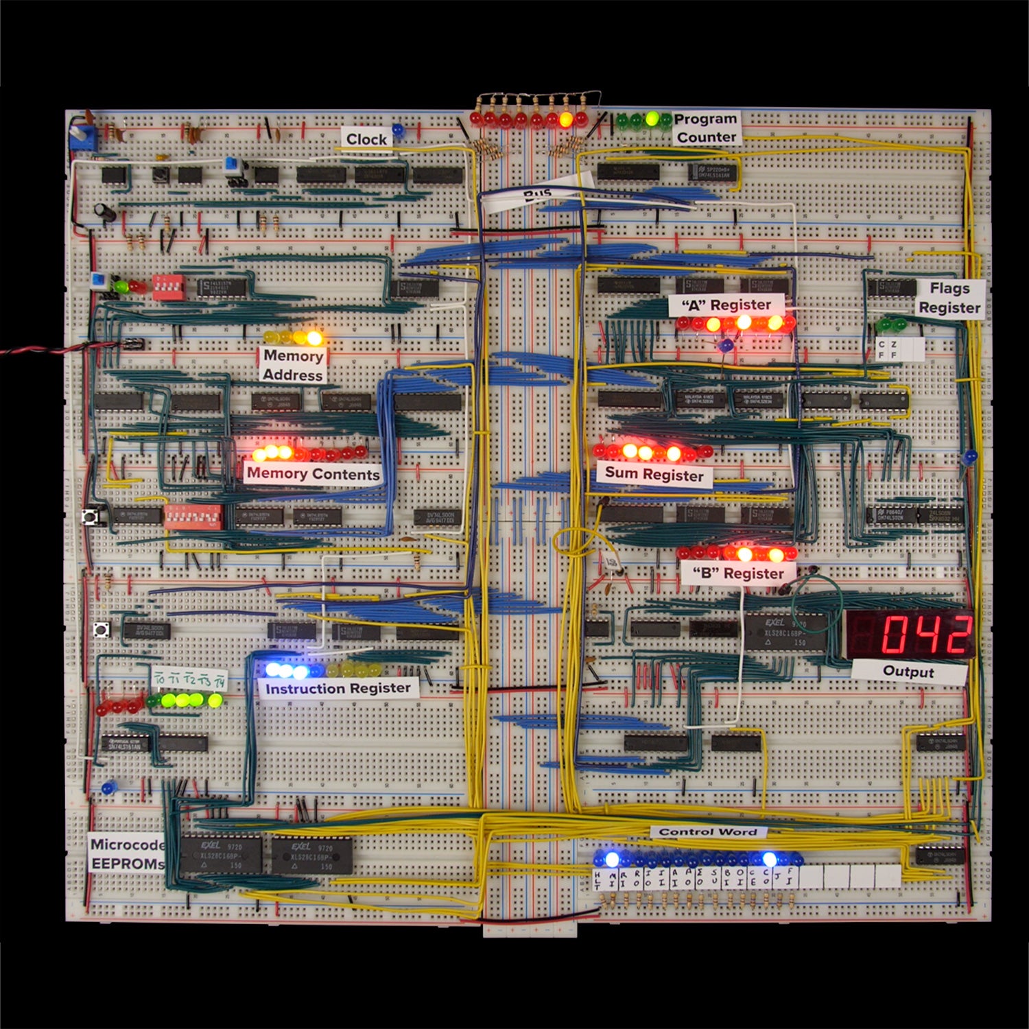
Example 8-bit breadboard computer assembly.
The CPU is organized as a set of hardware modules connected through a shared 8-bit bus. Control signals are generated by microcode stored in EEPROMs and executed as a sequence of micro-steps for each instruction.
The design includes:
- Clock and manual stepping
- Program counter
- RAM and memory address logic
- Instruction register
- A and B registers
- 8-bit arithmetic logic unit
- Carry and zero flags
- Output register
- EEPROM-based control logic
- Decimal output display
These previews are rendered from the editable KiCad source files. Select a schematic title to open its source.
Clock Module |
RAM |
Registers |
Instruction Register |
Product Register |
Program Counter |
Output Module |
Control Logic |
| Module | Role |
|---|---|
| Clock | Generates the processor clock and supports manual stepping |
| Program Counter | Tracks the address of the next instruction |
| RAM / Memory Address | Stores program instructions and data |
| Instruction Register | Holds the instruction currently being executed |
| A Register | Main accumulator |
| B Register | Secondary ALU operand |
| ALU | Performs addition and subtraction |
| Flags Register | Stores carry and zero flags |
| Output Register | Captures values for the output display |
| Control Logic | Generates control words for each instruction step |
| EEPROMs | Store microcode and display-decoder lookup data |
| Opcode | Instruction | Operation |
|---|---|---|
0000 |
NOP | No operation |
0001 |
LDA | Load a value from memory into A |
0010 |
ADD | Add a memory value to A |
0011 |
SUB | Subtract a memory value from A |
0100 |
STA | Store A in memory |
0101 |
LDI | Load an immediate value into A |
0110 |
JMP | Unconditional jump |
0111 |
JC | Jump if carry is set |
1000 |
JZ | Jump if zero is set |
1110 |
OUT | Copy A to the output register |
1111 |
HLT | Halt the clock |
The flags-aware microcode implements the conditional JC and JZ instructions.
8-bit-CPU/
├── assets/
│   └── schematics/  # Rendered KiCad previews
├── docs/
│   ├── project-completeness.md
│   └── references.md
├── firmware/
│   ├── display-decoder/
│   ├── eeprom-programmer/
│   └── microcode/
├── hardware/
│   ├── clock/
│   ├── control-logic/
│   ├── output/
│   └── ram-registers/
├── .gitignore
├── README.md
└── THIRD_PARTY_NOTICES.md
The KiCad sources are grouped by functional block.
The clock module provides an adjustable automatic clock and controlled manual pulses for debugging and step-by-step execution.
The project contains schematics for RAM, general registers, the instruction register, and the program counter.
The control section uses EEPROM-based microcode to generate a 16-bit control word for each micro-step.
The output module captures values from the bus and drives a decimal display through an EEPROM lookup table.
The architecture uses an 8-bit adder/subtractor together with carry and zero flags. A separate ALU KiCad schematic is not included in this repository.
firmware/eeprom-programmer/eeprom-programmer.ino
Arduino utility for programming compatible parallel EEPROM devices.
firmware/display-decoder/multiplexed-display.ino
Programs the EEPROM used by the decimal display, including signed two's-complement output.
firmware/microcode/microcode-eeprom-programmer.ino
Base CPU microcode for the core instruction set.
firmware/microcode/microcode-eeprom-with-flags.ino
Adds carry/zero flag handling and conditional jumps.
The microcode uses the following control lines:
HLT, MI, RI, RO, IO, II, AI, AO, EO, SU, BI, OI, CE, CO, J, and FI.
These signals coordinate register loading, bus output, RAM access, ALU operation, program-counter control, output capture, and flag updates.
KiCad hardware files can be opened with a recent KiCad version. Arduino sketches can be opened with the Arduino IDE or another compatible AVR development environment.
Start with the clock and register schematics, then review the control-logic schematic together with the microcode files to understand instruction execution.
The source package was reviewed before publication. Editor lock/history files and empty PCB placeholders were excluded so this repository contains the useful design artifacts rather than generated working files.
See docs/project-completeness.md for the project inventory and docs/references.md for local technical materials.
License terms for included firmware are listed in THIRD_PARTY_NOTICES.md.
Ahmed Youssef Bosha
Computer & Control Engineering
Faculty of Engineering, Tanta University
GitHub: R3Dzf